Электрическая схема автомобиля SKODA OKTAVIA
Электросхемы для легкового автомобиля Skoda Octavia. Все схемы в цветном виде и высоком качестве. Для бесплатного скачивания — кликните на схему. Представлены такие модули, как замок зажигания, коробка предохранителей, указатели поворота, аварийная сигнализация, выключатель стояночных фонарей, фары, двигатель и т д.
Схема Skoda Octavia — замок зажигания, реле для контакта X, коробка предохранителей
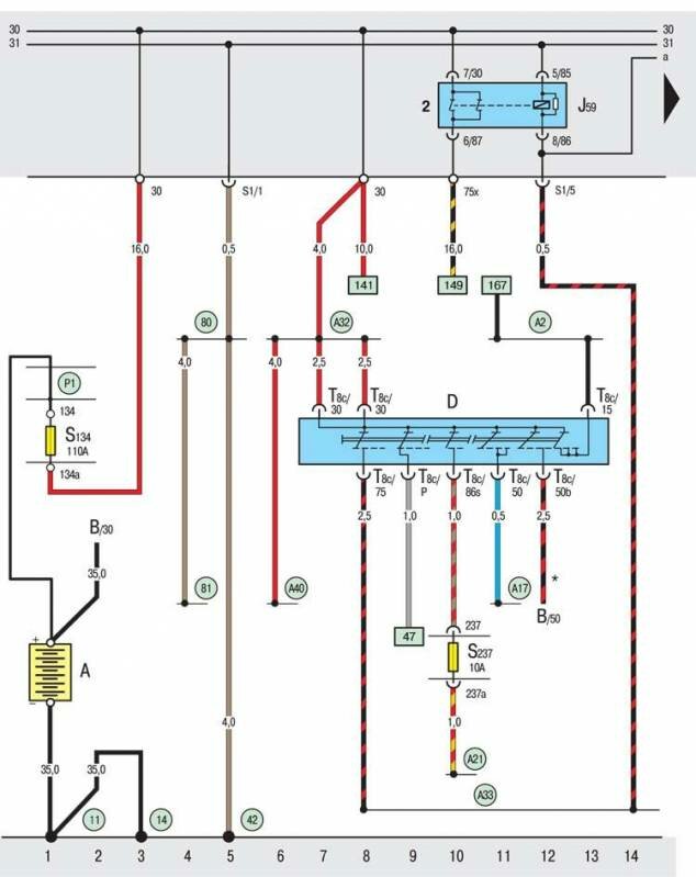
A – аккумуляторная батарея;
B – стартер Skoda Octavia ;
D – замок зажигания;
J59 – коммутационное реле для контакта Х;
S134 – предохранитель в коробке предохранителей на аккумуляторной батарее;
T8c – восьмиконтактный штекерныйразъем, на замке-выключателе зажигания и приборов;
11 – точка соединения на «массу» под аккумуляторной батареей слева;
14 – соединение на «массу» на коробке передач;
42 – точка соединения на «массу» рядом с колонкой рулевого управления;
80 – соединение на «массу» в жгуте проводов позади панели приборов;
81 – соединение на «массу» в жгуте проводов позади панели приборов;
А2 – соединение с положительным полюсом (15) в жгуте проводов позади панели приборов;
А17 – соединение (61) в жгуте проводов позади панели приборов;
А21 – соединение (86s) в жгуте проводов позади панели приборов;
А32 – соединение с положительным полюсом (30) в жгуте проводов позади панели приборов слева;
А33 – соединение (75) в жгуте проводов позади панели приборов слева;
А40 – соединение с положительным полюсом (30) в жгуте проводов позади панели приборов слева;
Р1 – соединение с положительным полюсом (30) в коробке предохранителей на аккумуляторной батареее;
Схема Skoda Octavia — указатели поворота, аварийная сигнализация, выключатель стояночных фонарей
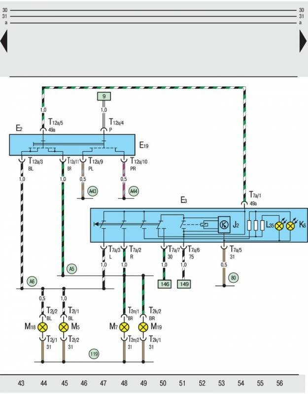
E2 – переключатель фонарей указателя поворота;
E3 – выключатель для системыаварийной светорой сигналазации;
E19 – включатель для стояночных фонарей;
J2 – прерыватель для фонарей системы аварийной световой сигнализации;
K6 – сигнализатор аварийной световой сигнализации;
L35 – лампа накаливания для освещения выключателя системы аварийной световой сигналазации;
M5 – лампа накаливания левого переднего фонаря указателя поворота;
M7 – лампа накаливания правого переднего фонаря указателя поворота;
M18 – лампа накаливания левого бокового повторителя указателя поворота;
M19 – лампа накаливания правого бокового повторителя указателя поворота;
T2j – двухконтактный штекерный разъем, на левом боковом повторителе указателя поворота;
T2k – двухконтактный штекерный разъем, на правом боковом повторителе указателя поворота;
T2l – двухконтактный штекерный разъем, на левом переднем фонаре указателя поворота;
T2m – двухконтактный штекерный разъем, на правом переднем фонаре указателя поворота;
T7a – семиконтактный штекерный разъем, на выключателе для системы аварийной световой сигнализации;
T12a – двенадцатиконтактный штекерный разъем, на переключателе фонарей указателя поворота;
80 – соединение на «массу» в жгуте проводов позади панели приборов;
119 – соединение на «массу» в кабельном жгуте впереди слева;
А5 – соединение с положительным полюсом (правый указатель поворота) в жгуте проводов позади панели щитка приборов слева;
А6 – соединение с положительным полюсом (левый указатель поворота) в жгуте проводов позади панели щитка приборов слева;
А43 – соединение (57L) в жгуте проводов позади панели приборов;
А44 – соединение (57R) в жгуте проводов позади панели приборов
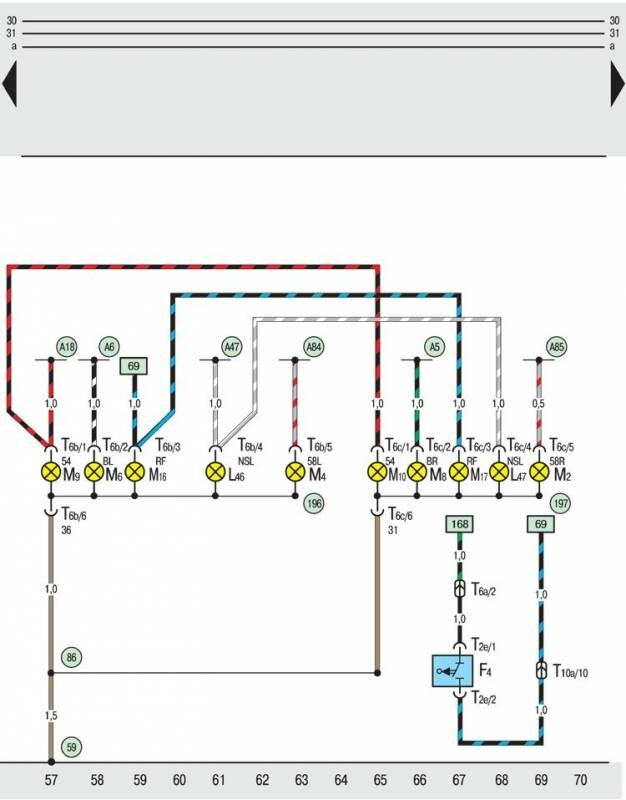
F4 – выключаель для фар заднего хода;
L46 – лампа накаливания левой задней противотуманной фары;
L47 – лампа накаливания правой задней противотуманной фары;
M2 – лампа накаливания правого заднего габаритного фонаря;
M4 – лампа накаливания левого заднего габаритного фонаря;
M6 – лампа накаливания левого заднего фонаря указателя поворота;
M8 – лампа накаливания правого заднего фонаря указателя поворота;
M9 – лампа накаливания левого фонаря сигнала торможения;
M10 – лампа накаливания правого фонаря сигнала торможения;
M16 – лампа накаливания левой фары заднего хода Skoda Octavia ;
M17 – лампа накаливания правой фары заднего хода;
T2e – двухконтактный штекерный разъем, на выключателе для фар заднего хода;
T6a – шестиконтактный штекерный разъем, в водонепроницаемом кожухе (красный);
T6b – шестиконтактный штекерный разъем, на левом заднем габаритном фонаре;
T6c – шестиконтактный штекерный разъем, на правом заднем габаритном фонаре;
T10a – десятиконтактный штекерный разъем, в водонепроницаемом кожухе (белый);
59 – точка соединения на «массу» вблизи от левого заднего габаритного фонаря;
86 – соединение на «массу» в заднем жгуте проводов;
196 – соединение на «массу» в левом заднем группированном световом приборе;
197 – соединение на «массу» в правом заднем группированном световом приборе;
А5 – соединение с положительным полюсом (правый указатель поворота) в жгуте проводов позади панели приборов слева;
А6 – соединение с положительным полюсом (левый указатель поворота) в жгуте проводов позади панели приборов слева;
А18 – соединение (54) в жгуте проводов позади панели приборов слева;
А47 – соединение (55) в жгуте проводов позади панели приборов;
А84 – соединение (58L) в жгуте проводов позади панели приборов слева;
А85 – соединение (58R) в жгуте проводов позади панели приборов слева
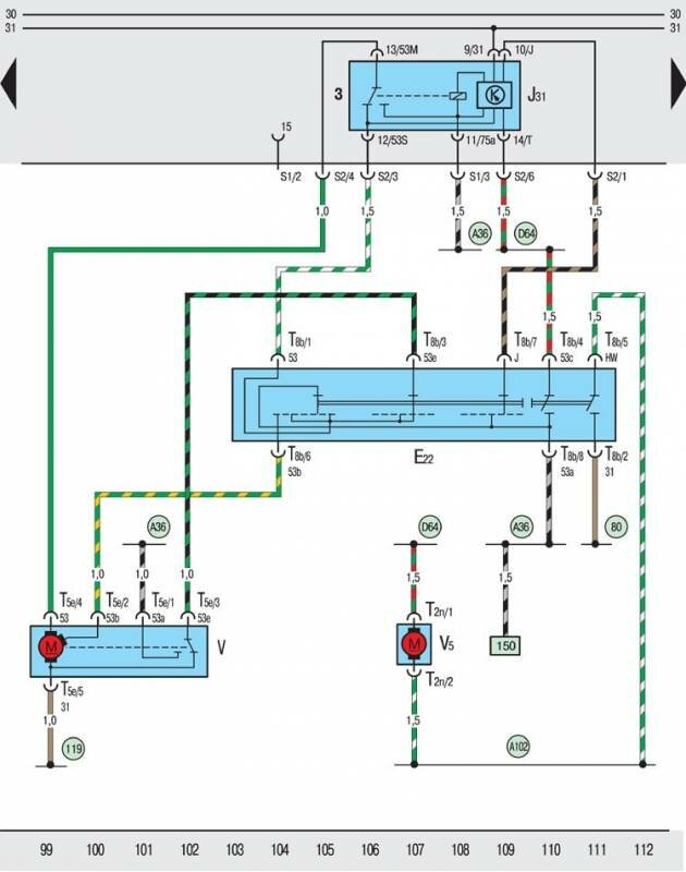
E22 – выключатель стеклоочистителей ветрового стекла;
J31 – выключатель двойного хода щеток стеклоочистителей;
T2n – двухконтактный штекерный разъем, на насосе стеклоочистителей переднего стекла;
T5e – пятиконтактный штекерный разъем, на электродвигателе стеклоочистителей;
T8b – восьмиконтактный штекерный разъем, на выключателе стеклоочистителей;
V – электродвигатель стеклоочистителей ветрового стекла;
V5 – насос стеклоочистителей переднего стекла;
80 – соединение на «массу» в жгуте проводов позади панели приборов;
119 – соединение на «массу» в жгуте проводов впереди слева;
A36 – соединение (53a) в жгуте проводов позади панели приборов слева;
A102 – соединение (стеклоочиститель) в жгуте проводов позади панели приборов;
D64 – соединение (53c) в жгуте проводов позади панели приборов
Электросхема Шкода Октавия — выключатель сигнала торможения, освещение багажника
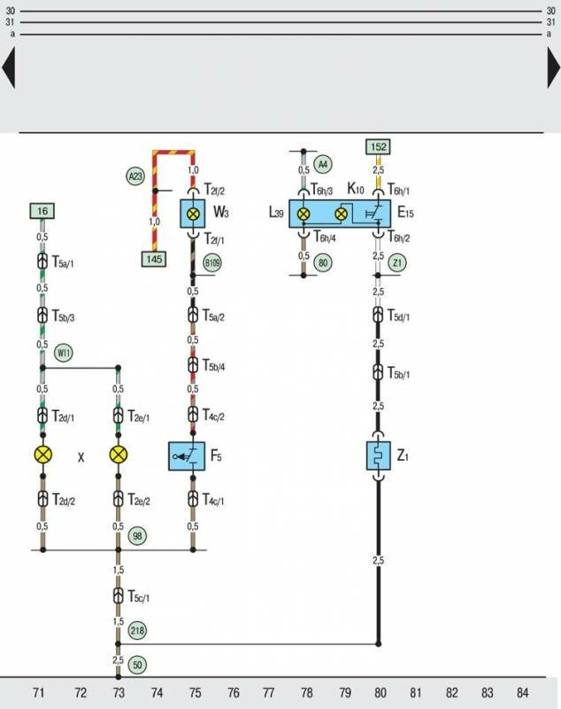
E15 – выключатель для обогрева заднего стекла;
F5 – включатель освещения багажника;
K10 – сигнализатор обогрева заднего стекла;
L39 – лампа накаливания для освещения выключателя обогрева заднего стекла;
T2d – двухконтактный штекерный разъем, на освещении номерного знака (левый);
T2e – двухконтактный штекерный разъем, на освещении номерного знака (правый);
T2f – двухконтактный штекерный разъем, на фонаре освещения багажника;
T4c – четырехконтактный штекерный разъем, на включателе освещения багажника;
T5a – пятиконтактный штекерный разъем, на стойке С слева (розовый);
T5b – пятиконтактный штекерный разъем, в крышке багажника слева (коричневый);
T5c – пятиконтактный штекерный разъем, в крышке багажника слева (черный);
T5d – пятиконтактный штекерный разъем, на стойке С слева (черный);
T6h – шестиконтактный штекерный разъем, на выключателе обогрева заднего стекла;
W3 – освещение багажника;
X – освещение номерного знака;
Z1 – обогреваемое заднее стекло;
50 – точка соединения на «массу» в багажнике слева;
80 – соединение на «массу» в жгуте проводов позади панели приборов;
98 – соединение на «массу» в жгуте проводов крышки багажника;
218 – соединение на «массу» в соединительном жгуте проводов крышки багажника;
А4 – соединение с положительным полюсом (58b) в жгуте проводов позади панели приборов;
А23 – соединение с положительным полюсом (30al) в жгуте проводов позади панели приборов слева;
В109 – соединение на «массу» в жгуте проводов позади слева (лишь для автомобилей с системой центрального управления замками двери);
W11 – соединение (58) в жгуте проводов крышки багажника;
Z1 – соединение с положительным полюсом в жгуте проводов позади панели приборов.
Розетка, коробка предохранителей, сигнал торможения Шкода Октавия
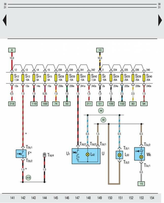
F – выключатель сигнала торможения Skoda Octavia ;
L42 – лампа накаливания для освещения штепсельной розеткаи;
L50 – лампа накаливания для освещения пепельницы сзади;
T2b – двухконтактный штекерный разъем, на выключателе сигнала торможения;
T2t – двухконтактный штекерный разъем, на лампе накаливания для освещения пепельницы сзади;
T2u – двухконтактный штекерный разъем, на фонаре освещения вещевого ящика;
T3d – трехконтактный штекерный разъем, на штепсельной розетке;
T5d – пятиконтактный штекерный разъем, на стойке С слева (черный);
U – штепсельная розетка;
U1 – прикуриватель;
W6 – освещение вещевого ящика;
80 – соединение на «массу» в жгуте проводов позади панели приборов;
A4 – соединение с положительным полюсом (58b) в жгуте проводов позади панели приборов;
A18 – соединение (54) в жгуте проводов позади щитка приборов слева;
Панель приборов, процессор, сигнализаторы, коробка предохранителей Skoda Octavia
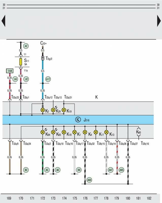
C – трехфазный генератор переменного тока;
J218 – процессор панели приборов;
K – панель приборов;
K1 – сигнализатор дальнего света фар;
K2 – сигнализатор генератора переменного тока;
K4 – сигнализатор габаритных огней;
K13 – сигнализатор задних противотуманных фар;
K17 – сигнализатор передних противотуманных фар;
K18 – сигнализатор указателей поворота прицепа;
K19 – сигнализатор пристегивания ремней безопасности;
K29 – сигнализатор накаливания (предварительного разогрева);
K60 – сигнализатор ближнего света фар;
K65 – сигнализатор левых фонарей указателя поворота;
K94 – сигнализатор правых фонарей указателя поворота;
T2g – двухконтактный штекерный разъем, в держателе на стартере;
T32a – 32-контактный штекерный разъем, на панели приборов (синий);
T32b – 32-контактный штекерный разъем, на панели приборов (зеленый);
80 – соединение на «массу» в жгуте проводов позади панели приборов;
A2 – соединение с положительным полюсом (15) в жгуте проводов позади панели приборов;
A5 – соединение с положительным полюсом (правый указатель поворота) в жгуте проводов позади панели щитка приборов слева;
A6 – соединение с положительным полюсом (левый указатель поворота) в жгуте проводов позади панели щитка приборов слева;
A17 – соединение (61) в жгуте проводов позади панели приборов;
A47 – соединение (55) в жгуте проводов позади панели приборов;
A84 – соединение (58L) в жгуте проводов позади панели приборов слева;
A85 – соединение (58R) в жгуте проводов позади панели приборов слева;
B9 – соединение (56aR) в жгуте проводов позади панели приборов слева;
U2 – соединение с положительным полюсом (15) в жгуте проводов позади панели приборов (лишь для автомобилей с АКПП);
U4 – соединение с положительным полюсом (30) в жгуте проводов позади панели приборов (лишь для автомобилей с АКПП)
Сигнал уровня тормозной жидкости автомобиля
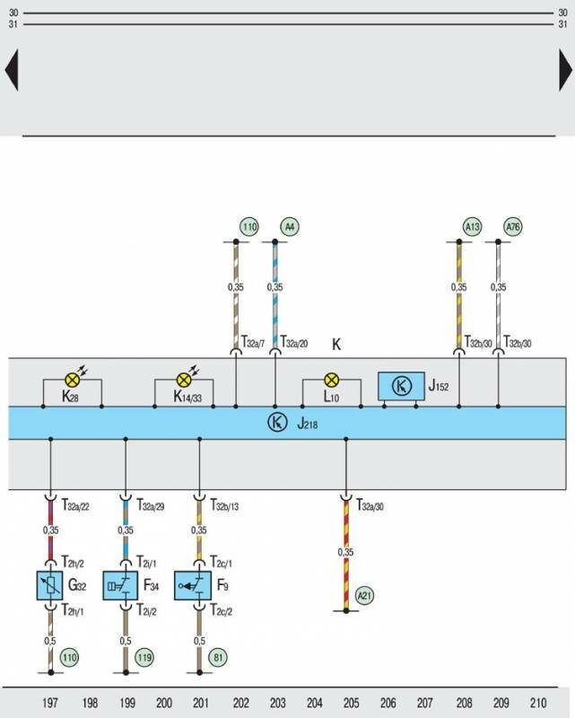
F9 – выключатель для сигнализатора включения стояночной тормозной системы;
F34 – контакт предупредительного сигнала при аварийном падении уровня тормозной жидкости;
G32 – датчик уровня охлаждающей жидкости;
J152 – звуковая сигнализация включения фар;
J218 – процессор панели приборов;
K – панель приборов Skoda Octavia ;
K14/ 33 – сигнализатор включения стояночной тормозной системы/ уровня тормозной жидкости;
K28 – сигнализатор температуры и уровня охлаждающей жидкости;
L10 – лампа накаливания для освещения панели приборов;
T2c – двухконтактный штекерный разъем, на выключателе для сигнализатора включения стояночной тормозной системы;
T2h – двухконтактный штекерный разъем, на датчике уровня охлаждающей жидкости;
T2i – двухконтактный штекерный разъем, на контакте предупредительного сигнала при аварийном падении уровня тормозной жидкости;
T32a – 32-контактный штекерный разъем, на панели приборов (синий);
T32b – 32-контактный штекерный разъем, на панели приборов (зеленый);
81 – соединение на «массу» в жгуте проводов позади панели приборов;
110 – соединение на «массу» в жгуте проводов позади панели приборов;
119 – соединение на «массу» в кабельном жгуте впереди слева;
A4 – соединение с положительным полюсом (58b) в жгуте проводов позади панели приборов;
A13 – соединение (дверные выключатеи освещения в кузове) в жгуте проводов позади панели приборов;
A21 – соединение (86s) в жгуте проводов позади панели приборов;
A76 – соединение (диагностический провод K) в жгуте проводов позади панели приборов
Иммобилизатор, панель приборов, процессор, сигнализаторы, спидометр — электросхема
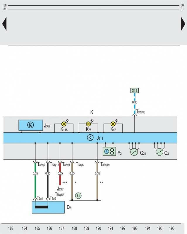
D2 – обмотка считывания иммобилизатора (на замке-выключателе зажигания и приборов);
G3 – указатель температуры охлаждающей жидкости;
G21 – спидометр Skoda Octavia ;
J217 – блок управления АКПП;
J218 – процессор панели приборов;
J362 – блок управления иммобилизатором;
K – панель приборов;
K47 – сигнализатор противоблокировочного устройства тормозной системы «ABS»;
K75 – сигнализатор системы надувных подушек безопасности «Airbag»;
K115 – сигнализатор иммобилизатора;
T2s – двухконтактный штекерный разъем, на обмотке считывания иммобилизатора;
T32a – 32-контактный штекерный разъем, на панели приборов (синий);
T32b – 32-контактный штекерный разъем, на панели приборов (зеленый);
T68a – 68-контактный штекерный разъем, на блоке управления АКПП;
Y2 – цифровые часы Skoda Octavia ;
81 – соединение на «массу».
Цвета предохранителей Шкода Октавия
Источник
Руководство Блоки управления Skoda Octavia 3 FL (A7) распиновка разьемов, передняя часть автомобиля
Control units in the front part of the vehicle
Overview of the control units (only for vehicles with left-hand drive)
1 — Multi-function steering wheel control unit -J453-
2 — Ignition starter switch -D-
3 — Steering column electronics control unit -J527-
4 — Electronic steering column lock control unit -J764-
5 — Light switch -E1-
6 — Control unit in dash panel insert -J285- / Immobilizer control unit -J362-
7 — Interface for entry and start system -J965-
8 — Control unit for emergency call module and communication unit -J949-
9 — Onboard control unit -J519-
10 — Parking aid control unit -J446- / park steering assistant control unit -J791-
11 — Data bus diagnostic interface -J533-
12 — Automatic gearbox control unit -J217-
13 — Wiper motor control unit -J400-
14 — Control unit for cornering light and headlight range control -J745-
15 — Battery monitor control unit -J367-
16 — Control unit for left light control -J1018-
17 — Engine control unit -J623-
18 — Power output module 1 for left LED headlight -A31-
19 — Daytime running light and left parking light control unit -J860-
20 — Double clutch gearbox mechatronics -J743-
21 — NOx sensor control unit — J583-
22 — Radiator fan control unit -J293-
23 — Control unit for clearance control -J428-
24 — Power steering control unit -J500-
25 — Control unit for transverse locks -J647-
26 — Structure-borne noise control unit -J869-
27 — Right daytime running light and parking light control unit -J861-
28 — Control unit for right light control -J1023-
29 — Power output module 1 for right LED headlight -A27-
30 — Additional heater control unit -J364-
31 — ABS control unit -J104-
32 — Airbag control unit -J234-
33 — Control unit for IT 1 -J794-
for MIB standard, high
34 — Control unit for IT 1 -J794-
for MIB entry
35 — Heater control unit -J65- / Air conditioning system control unit -J301- / Climatronic control unit -J255-
36 — Front camera for diver assistance systems -R242-/main beam assistant control unit -J844-
1.3 Steering column electronics control unit -J527-
Note: The version of the steering column electronics control unit can differ depending on the equipment.
1.3.1 Pin assignment
A — Steering column electronics control unit -J527-
B — 12-pin connector, — T12a
C — 8-pin connector
D — 8-pin connector
E — 6-pin connector
F — 16-pin connector, — T16a
G — 9-pin connector
H — 4-pin connector, T4w
A — Steering column electronics control unit -J527-
B — 12-pin connector -T12a- :
1 — not assigned
2 — not assigned
3 — Airbag (+)
4 — Airbag (-)
5 — not assigned
6 — not assigned
7 — Terminal 31 for horn activation -H- , for multi-function steering wheel control unit -J453-
8 — Horn activation -H- input (does not apply to vehicles with the multifunction steering wheel)
9 — LIN bus (only for vehicles with multi-function steering wheel)
10 — Terminal 15 for multi-function steering wheel control unit -J453-
11 — not assigned
12 — not assigned
C — 8-pin connector — Turn signal switch -E2- , , Headlight dipper and flasher switch -E4- :
1 — not assigned
2 — not assigned
3 — Terminal 31 for turn signal switch -E2- , for headlight dipper/flasher switch -E4-
4 — High beam
5 — Flashing lights
6 — Headlight flasher
7 — Headlight flasher
8 — Wake up for turn signals
D — 8-pin connector — Ignition starter switch -D- , , Ignition key withdrawal lock solenoid -N376- :
1 — Input of ignition starter switch terminal -D- 50 (without entry and start authorisation)
2 — not assigned
3 — Output of ignition starter switch -D- terminal 30 (without entry and start authorisation)
4 — Input of ignition starter switch -D- terminal 86s (without entry and start authorisation)
5 — Input of ignition starter switch terminal -D- 15 (without entry and start authorisation)
6 — Input of ignition starter switch terminal -D- 15 (without entry and start authorisation)
7 — Terminal 30 for ignition key withdrawal lock solenoid -N376- (without entry and start authorisation)
8 — Terminal 31 for ignition key withdrawal lock solenoid -N376- (without entry and start authorisation)
E — 6-pin connector — Intermittent wiper switch -E22- , Rear wiper switch -E34- , Intermittent wiper control -E38- , Multi-function display call-up button -E86- , Multi-function display memory switch -E109- :
1 — Terminal 31 for intermittent wiper control -E38- , for multi-function display call-up button -E86- , for multi-function display memory switch -E109-
2 — Input of intermittent wiper control -E38-
3 — Input of multi-function display call-up button -E86- , of multi-function display memory switch -E109-
4 — Input of rear wiper switch -E34-
5 — Input of intermittent wiper switch -E22-
6 — Terminal 31 for intermittent wiper switch -E22- , for rear wiper switch -E34-
F — 16-pin connector -T16a- :
1 — Input — terminal 30
2 — Input — terminal 31
3 — Convenience CAN bus, low
4 — Convenience CAN bus, high
5 — Output for CCS
6 — Output of engine control unit -J623- terminal 50 (without entry and start authorisation)
7 — Output of Onboard control unit -J519- terminal 86s (without entry and start authorisation)
8 — not assigned
9 — not assigned
10 — not assigned
11 — Input of selector lever switch locked in position P -F319- (only on vehicles with automatic gearbox)
12 — not assigned
13 — not assigned
14 — Output of Onboard control unit -J519- terminal 15 (without entry and start authorisation)
15 — not assigned
16 — Output of Onboard control unit -J519- terminal 15 (without entry and start authorisation)
G — 9-pin connector — CCS switch -E45- , CCS SET button -E227- :
1 — Terminal 15 for switch for ESC -E45-
2 — CCS OFF
3 — not assigned
4 — RES (+), SET (-)
5 — CCS ON/OFF
6 — Terminal 31 for CCS switch -E45- , for CCS SET button -E227-
7 — not assigned
8 — not assigned
9 — not assigned
H — 4-pin connector -T4w- :
3 — Airbag (+)
4 — Airbag (-)
5 — not assigned
6 — not assigned
A — Steering column electronics control unit -J527-
B — 12-pin connector, — T12a
C — 9-pin connector
D — 7-pin connector
E — 6-pin connector
F — 16-pin connector, — T16a
G — 6-pin connector
H — 4-pin connector, T4w
A — Steering column electronics control unit -J527-
B — 12-pin connector -T12a- :
1 — not assigned
2 — not assigned
3 — Airbag (+)
4 — Airbag (-)
5 — not assigned
6 — not assigned
7 — Terminal 31 for horn activation -H- , for multi-function steering wheel control unit -J453-
8 — Input of horn activation -H-
9 — LIN bus (only for vehicles with multi-function steering wheel)
10 — Terminal 30 for multi-function steering wheel control unit -J453-
11 — not assigned
12 — not assigned
C — 9-pin connector — Turn signal switch -E2- , , Headlight dipper and flasher switch -E4- :
1 — RES (+), SET (-)
2 — CCS ON/OFF
3 — CCS OFF
4 — Terminal 31 for CCS switch -E45- , for CCS SET button -E227- , for function selection switch 2 -E272-
5 — Wake up for turn signals
6 — Indicator lights (LEFT)
7 — Terminal 31 for turn signal switch -E2- , for headlight dipper/flasher switch -E4-
8 — Headlight flasher/main beam
9 — Indicator lights (RIGHT)
D — 7-pin connector — Ignition starter switch -D- , , Ignition key withdrawal lock solenoid -N376- :
1 — Output of ignition starter switch -D- terminal 30 (without entry and start authorisation)
2 — Input of ignition starter switch terminal -D- 15 (without entry and start authorisation)
3 — Input of ignition starter switch terminal -D- 15 (without entry and start authorisation)
4 — Input of ignition starter switch -D- terminal 86s (without entry and start authorisation)
5 — Input of ignition starter switch terminal -D- 50 (without entry and start authorisation)
6 — Terminal 30 for ignition key withdrawal lock solenoid -N376- (without entry and start authorisation)
7 — Terminal 31 for ignition key withdrawal lock solenoid -N376- (without entry and start authorisation)
E — 6-pin connector — Intermittent wiper switch -E22- , Rear wiper switch -E34- , Intermittent wiper control -E38- , Multi-function display call-up button -E86- , Multi-function display memory switch -E109- :
1 — Input of multi-function display call-up button -E86- , of multi-function display memory switch -E109-
2 — Terminal 31 for intermittent wiper control -E38- , for multi-function display call-up button -E86- , for multi-function display memory switch -E109-
3 — Input of intermittent wiper control -E38-
4 — Input of intermittent wiper switch -E22-
5 — Terminal 31 for intermittent wiper switch -E22- , for rear wiper switch -E34-
6 — Input of rear wiper switch -E34-
F — 16-pin connector -T16a- :
1 — Input — terminal 30
2 — Input — terminal 31
3 — Convenience CAN bus, low
4 — Convenience CAN bus, high
5 — Output for CCS
6 — Output of engine control unit -J623- terminal 50 (without entry and start authorisation)
7 — Output of Onboard control unit -J519- terminal 86s (without entry and start authorisation)
8 — not assigned
9 — not assigned
10 — not assigned
11 — Input of selector lever switch locked in position P -F319- (only on vehicles with automatic gearbox)
12 — not assigned
13 — not assigned
14 — Output of Onboard control unit -J519- terminal 15 (without entry and start authorisation)
15 — not assigned
16 — Output of Onboard control unit -J519- terminal 15 (without entry and start authorisation)
G — 6-pin connector — CCS switch -E45- , CCS SET button -E227- :
1 — not assigned
2 — not assigned
3 — not assigned
4 — not assigned
5 — not assigned
6 — not assigned
H — 4-pin connector -T4w- :
1 — Airbag (+)
2 — Airbag (-)
3 — not assigned
4 — not assigned
A — Steering column electronics control unit -J527-
B — 12-pin connector, — T12a
C — 9-pin connector
D — 7-pin connector
E — 6-pin connector
F — 14-pin connector, — T14a
G — 6-pin connector
H — 4-pin connector, T4w
I — 2-pin connector — T2az
A — Steering column electronics control unit -J527-
B — 12-pin connector -T12a- :
1 — not assigned
2 — not assigned
3 — Airbag (+)
4 — Airbag (-)
5 — not assigned
6 — not assigned
7 — Terminal 31 for horn activation -H- , for multi-function steering wheel control unit -J453-
8 — Input of horn activation -H-
9 — LIN bus (only for vehicles with multi-function steering wheel)
10 — Terminal 30 for multi-function steering wheel control unit -J453-
11 — not assigned
12 — not assigned
C — 9-pin connector — Turn signal switch -E2- , , Headlight dipper and flasher switch -E4- :
1 — RES (+), SET (-)
2 — CCS ON/OFF
3 — CCS OFF
4 — Terminal 31 for CCS switch -E45- , for CCS SET button -E227- for function selection switch 2 -E272-
5 — Wake up for turn signals
6 — Indicator lights (LEFT)
7 — Terminal 31 for turn signal switch -E2- , for headlight dipper/flasher switch -E4-
8 — Headlight flasher/main beam
9 — Indicator lights (RIGHT)
D — 7-pin connector — Ignition starter switch -D- , , Ignition key withdrawal lock solenoid -N376- :
1 — Output of ignition starter switch -D- terminal 30 (without entry and start authorisation)
2 — Input of ignition starter switch terminal -D- 15 (without entry and start authorisation)
3 — Input of ignition starter switch terminal -D- 15 (without entry and start authorisation)
4 — Input of ignition starter switch -D- terminal 86s (without entry and start authorisation)
5 — Input of ignition starter switch terminal -D- 50 (without entry and start authorisation)
6 — Terminal 30 for ignition key withdrawal lock solenoid -N376- (without entry and start authorisation)
7 — Terminal 31 for ignition key withdrawal lock solenoid -N376- (without entry and start authorisation)
E — 6-pin connector — Intermittent wiper switch -E22- , Rear wiper switch -E34- , Intermittent wiper control -E38- , Multi-function display call-up button -E86- , Multi-function display memory switch -E109- :
1 — Input of multi-function display call-up button -E86- , of multi-function display memory switch -E109-
2 — Terminal 31 for intermittent wiper control -E38- , for multi-function display call-up button -E86- , for multi-function display memory switch -E109-
3 — Input of intermittent wiper control -E38-
4 — Input of intermittent wiper switch -E22-
5 — Terminal 31 for intermittent wiper switch -E22- , for rear wiper switch -E34-
6 — Input of rear wiper switch -E34-
F — 14-pin connector -T14h- :
1 — Input — terminal 30
2 — Input — terminal 30
3 — not assigned
4 — Input — terminal 31
5 — Convenience CAN bus, low
6 — Convenience CAN bus, high
7 — Output for CCS
8 — Input — terminal 31
9 — Input of selector lever switch locked in position P -F319- (only on vehicles with automatic gearbox)
10 — Output of Onboard control unit -J519- terminal 15 (without entry and start authorisation)
11 — Output of Onboard control unit -J519- terminal 15 (without entry and start authorisation)
12 — Output of Onboard control unit -J519- terminal 86s (without entry and start authorisation)
13 — Output of engine control unit -J623- terminal 50 (without entry and start authorisation)
14 — LIN bus (only for vehicles with multi-function steering wheel)
G — 6-pin connector — CCS switch -E45- , CCS SET button -E227- :
1 — not assigned
2 — not assigned
3 — not assigned
4 — not assigned
5 — not assigned
6 — not assigned
H — 4-pin connector -T4w- :
1 — Airbag (+)
2 — Airbag (-)
3 — not assigned
4 — not assigned
I — 2-pin connector -T2az- :
1 — Steering wheel heating (+)
2 — Steering wheel heating (-)
1.4 Electronic steering column lock control unit -J764-
1.4.1 Fitting location (only for left-hand drive vehicles — to July 2018)
A — Electronic steering column lock control unit -J764-
B — 16-pin connector, at wiring harness — T16e
1.4.2 Fitting location (only for left-hand drive vehicles — from July 2018):
A — Electronic steering column lock control unit -J764-
B — 4-pin connector, at wiring harness — T4cc
1.4.3 Fitting location (only for right-hand drive vehicles — to July 2018):
A — Electronic steering column lock control unit -J764-
B — 16-pin connector, at wiring harness — T16e
1.4.4 Fitting location (only for right-hand drive vehicles — from July 2018):
A — Electronic steering column lock control unit -J764-
B — 4-pin connector, at wiring harness — T4cc
1.5 Interface for entry and start system -J965-
1.5.1 Fitting location (only for left-hand drive vehicles — to July 2018)
Below the dash panel, near centre console -arrow-.
1.5.2 Fitting location (only for left-hand drive vehicles — from July 2018):
A — Interface for entry and start system -J965-
B — 40-pin connector, at wiring harness — T40a
1.5.3 Fitting location (only for right-hand drive vehicles — to July 2018):
Below the dash panel, near centre console -arrow-.
1.5.4 Fitting location (only for right-hand drive vehicles — from July 2018):
A — Interface for entry and start system -J965-
B — 40-pin connector, at wiring harness — T40a
1.5.5 Pin assignment (to July 2018)
A — Interface for entry and start system -J965-
B — 32-pin connector, at wiring harness — T32a
1.6 Control unit for emergency call module and communication unit -J949-
1.6.1 Fitting location (only for left-hand drive vehicles):
A — Control unit for emergency call module and communication unit -J949-
B — 2-pin connector, at wiring harness — T2aw
C — 26-pin connector, at wiring harness — T26d
1.6.2 Fitting location (only for right-hand drive vehicles):
A — Control unit for emergency call module and communication unit -J949-
B — 2-pin connector, at wiring harness — T2aw
C — 26-pin connector, at wiring harness — T26d
1.7 Onboard control unit — J519
1.7.1 Pin assignment, as of February 2017
A — 73-pin connector — T73a
B — 46-pin connector -T46b
C — 73-pin connector — T73c
73-pin connector -T73a- :
1 — Input (30) — front seat heating supply
2 — Output for heated driver’s seat -Z6- , heated driver seat backrest -Z7- (only for left-hand drive vehicles)
— Output for heated front passenger’s seat -Z8- , heated front passenger’s seat backrest -Z9- (only for right-hand drive vehicles)
3 — Output for tank filler flap locking motor -V155-
4 — Output for tank filler flap locking motor -V155-
5 — Output for heated front passenger’s seat -Z8- , heated front passenger’s seat backrest -Z9- (only for left-hand drive vehicles)
— Output for heated driver’s seat -Z6- , heated driver seat backrest -Z7- (only for right-hand drive vehicles)
6 — Output for central locking motor in rear right door, lock -V215- , motor for SAFE function of central locking in rear right door -V164-
7 — Output for central locking motor in rear right door, lock -V215-
8 —
9 — Output for central locking motor in rear lid -V53-
10 —
11 —
12 — Input — terminal 31
13 — Output for terminal 15 voltage supply relay -J329-
14 — Output — signal — terminal 15
15 — LIN bus — Sensor for interior monitoring -G273- . Encoder for vehicle incline -G384- . Control unit for sunroof -J245-
16 — CAN H, convenience
17 — CAN L, convenience
18 —
19 —
20 —
21 —
22 — Output for vehicle level sensor, rear left -G76-
23 — Input of vehicle level sensor, rear left -G76-
24 —
25 —
26 —
27 —
28 —
29 — Input of fog light and rear fog light switch -E23-
30 —
31 — Input of interior button for central locking driver’s side -E308-
32 — Input of rear lid handle release button -E234-
33 — Input of central locking lock unit, rear right -F223-
34 —
35 — Input of central locking lock unit, rear left -F222-
36 — Output for motor for SAFE function of central locking in rear left door -V163-
37 — Output for motor for SAFE function of central locking in rear right door -V164-
38 —
39 —
40 —
41 —
42 —
43 — Input of light switch -E1- terminal 58
44 — Input of steering column electronics control unit -J527- — terminal 15 (for vehicles without entry and start authorisation)
— Steering column electronics control unit -J764- input, terminal 15 (for vehicles with entry and start authorisation)
45 —
46 — Input of light switch -E1- terminal TFL
47 — Input of steering column electronics control unit -J527- — terminal 15 (for vehicles without entry and start authorisation)
— Steering column electronics control unit -J764- input, terminal 15 (for vehicles with entry and start authorisation)
48 — Input of door contact switch, rear right -F11-
49 —
50 — Input of door contact switch, rear left -F10-
51 — Input of deactivation button of interior monitoring and vehicle inclination -E616-
52 — Input of rear lid lock unit -F256- terminal 31
53 — Closing unit for tailgate -F256- input (on vehicles with electric tailgate opening)
54 — Input of steering column electronics control unit -J527- — terminal 86s (for vehicles without entry and start authorisation)
— Steering column electronics control unit -J764- input, terminal 86s (for vehicles with entry and start authorisation)
55 —
56 —
57 — Output for bulb for high level brake light -M25-
58 —
59 — Output for number plate light, left -X4- , number plate light, right -X5-
60 — Output for turn signal bulb, rear left -M6-
61 — Output for rear window wiper motor -V12-
62 — Output for rear window wiper motor -V12-
63 — Input — terminal 31
64 — Output for reversing light bulb, right -M17- , Automatic anti-dazzle interior mirror -Y7- , rear view camera -R189-
65 — Output for tail light bulb, right -M2-
66 — Input (30) — light supply
67 —
68 — Output for central locking motor in rear left door, lock -V214- , motor for SAFE function of central locking in rear left door -V163-
69 — Output for central locking motor in rear left door, lock -V214-
70 —
71 — Output for brake light bulb, left -M9-
72 — Output for rear fog light bulb, left -L46-
73 — Input — terminal 30
46-pin connector -T46b- :
1 — Output for Right lamp for dipped beam headlights -M31- , Power output module 1 for right headlight -A27-
2 — Lamp for right high beam headlight -M32- output (not for Octavia RS)
— Power module 1 output for left LED headlights -A31-
3 — Output for left side light bulb -M1-
4 — Output for control unit for left daytime running light and side light -J860-
— Output for lamp for right fog lights -L23- . Right static cornering light -M52- (only for Octavia RS)
5 — Output for fog light bulb, right -L23- , static cornering light, right -M52-
6 — Output for left headlight range control motor -V48- , right headlight range control motor -V49- terminal 31
7 — Output for windscreen and rear window washer pump -V59-
8 — Output for windscreen and rear window washer pump -V59-
9 — Output for heating resistance for injection nozzle, left -Z20- , heating resistance for injection nozzle, right -Z21-
10 — Output for control unit for left daytime running light and side light -J860-
— Output for Lamp for left fog lights -L22- . Left static cornering light -M51- (only for Octavia RS)
11 — Input of reversing light switch -F4-
12 — Input of brake lining/pad wear sender, front right -G35-
13 — Input of brake fluid level warning contact -F34-
14 — Input of bonnet contact switch -F266-
15 —
16 — Input of coolant shortage indicator sender -G32-
17 — Input of vehicle level sensor, front right -G78-
18 — Output for vehicle level sensor, front left -G78-
19 — Output for sender earth — terminal 31
20 — Output for turn signal bulb, front right -M7-
21 — Output for control unit for right daytime running light and side light -J861-
— Output for lamp for right fog lights -L23- . Right static cornering light -M52- (only for Octavia RS)
22 —
23 —
24 — Output for horn relay -J413-
25 —
26 — Output for heated windscreen relay -J47-
27 — Input of ambient temperature sensor -G17-
28 — Input of windscreen washer fluid level sender -G33-
29 —
30 — LIN bus — wiper motor control unit -J400-
31 — LIN Bus — signal horn for anti-theft alarm system -H8-
32 — Output for control unit for right daytime running light and side light -J861-
— Output for Lamp for left fog lights -L22- . Left static cornering light -M51- (only for Octavia RS)
33 — Output for headlight range control motor, left -V48- , headlight range control motor, right -V49-
34 —
35 — Output for side light bulb, right -M3-
36 — Output for turn signal bulb, front left -M5-
37 —
38 —
39 — Output for Lamp for left high beam headlight -M30- (not for Octavia RS)
— Output for Power module 1 for right LED headlights -A27-
40 —
41 —
42 —
43 —
44 — Output for headlight range control motor, left -V48- , headlight range control motor, right -V49-
45 — Output for fog light bulb, left -L22- , static cornering light, left -M51-
46 — Output for headlight washer system pump -V11-
73-pin connector -T73c- :
1 — Input (30) — light supply
2 —
3 —
4 —
5 — Output for left lamp for dipped beam headlights -M29- , power output module 1 for left headlight -A31-
6 — Output for right rear fog light lamp -L47-
7 —
8 — Output for brake light bulb, right -M10-
9 —
10 — Output for tail light bulb, left -M4-
11 — Output for reversing light bulb, left -M16-
12 — Output for interior light — terminal 30g
13 —
14 — Input of interface for entry and start authorisation -J965- (wake up wire)
15 — Input of light switch -E1- terminal 56
16 — Input of light switch -E1- (AFL)
17 —
18 —
19 —
20 —
21 — Output for Warning light for operational profile selection -K280-
22 —
23 —
24 — Output for heated rear window relay -J9-
25 —
26 —
27 —
28 — Input of humidity sender -G355- , air humidity, rain and light detector sensor -G823-
29 — Output for Light for front left door contour lighting -L251- , Light for front right door contour lighting -L252- , Light for rear left door contour lighting -L253- , Light
for rear right door contour lighting -L254-
30 —
31 — Output for turn signal bulb, rear right -M8-
32 — Output for deactivation warning light of interior monitoring and vehicle inclination -K248-
33 —
34 — Input of exterior mirror heating button -E735-
35 —
36 —
37 —
38 —
39 —
40 — Input of Temperature sensor for front passenger seat -G60- (only for left-hand drive vehicles)
— Input of Temperature sensor for driver’s seat -G59- (only for right-hand drive vehicles)
41 —
42 — Input of hazard warning lights button -E229-
43 — Input of Temperature sensor for driver’s seat -G59- (only for left-hand drive vehicles)
— Input of Temperature sensor for front passenger’s seat -G60- (only for right-hand drive vehicles)
44 —
45 —
46 — Output for heated front seat control unit -J786-
47 — Output for control light for interior locking warning light, driver side -K174-
48 — Output for hazard warning light system warning light -K6- , bulb for button illumination -L76-
49 —
50 —
51 — Output for start/stop operation warning light -K259-
52 —
53 —
54 —
55 —
56 — Output for sender earth — terminal 31
57 — Output for vehicle level sensor, rear left -G76-
58 — Input of brake light switch -F-
59 —
60 — Input of start/stop operation button -E693-
61 —
62 — Output — terminal 58d
63 — Input — terminal 31
64 —
65 —
66 —
67 — Output for interior light, Deactivation button of interior monitoring and vehicle incline -E616- — Terminal 31 (door contact switch)
68 —
69 —
70 —
71 —
72 — Output for left footwell light -W9- , right footwell light -W10- , rear left footwell light -W45- , rear right footwell light -W46-
73 — Input — terminal 30
1.7.2 Pin assignment, as of May 2017
A — 73-pin connector — T73a
B — 46-pin connector -T46b
C — 73-pin connector — T73c
73-pin connector -T73a- :
1 — Input (30) — front seat heating supply
2 — Output for heated driver’s seat -Z6- , heated driver seat backrest -Z7- (only for left-hand drive vehicles0
— Output for heated front passenger’s seat -Z8- , heated front passenger’s seat backrest -Z9- (only for right-hand drive vehicles)
3 — Output for tank filler flap locking motor -V155-
4 — Output for tank filler flap locking motor -V155-
5 — Output for heated front passenger’s seat -Z8- , heated front passenger’s seat backrest -Z9- (only for left-hand drive vehicles)
— Output for heated driver’s seat -Z6- , heated driver seat backrest -Z7- (only for right-hand drive vehicles)
6 — Output for central locking motor in rear right door, lock -V215- , motor for SAFE function of central locking in rear right door -V164-
7 — Output for central locking motor in rear right door, lock -V215-
8 —
9 — Output for central locking motor in rear lid -V53-
10 —
11 —
12 — Input — terminal 31
13 — Output for terminal 15 voltage supply relay -J329-
14 — Output — signal — terminal 15
15 — LIN bus — Sensor for interior monitoring -G273- . Encoder for vehicle incline -G384- . Control unit for sunroof -J245-
16 — CAN H, convenience
17 — CAN L, convenience
18 —
19 —
20 —
21 —
22 — Output for vehicle level sensor, rear left -G76-
23 — Input of vehicle level sensor, rear left -G76-
24 —
25 —
26 —
27 —
28 —
29 — Input of fog light and rear fog light switch -E23-
30 —
31 — Input of interior button for central locking driver’s side -E308-
32 — Input of rear lid handle release button -E234-
33 — Input of central locking lock unit, rear right -F223-
34 —
35 — Input of central locking lock unit, rear left -F222-
36 — Output for motor for SAFE function of central locking in rear left door -V163-
37 — Output for motor for SAFE function of central locking in rear right door -V164-
38 —
39 —
40 —
41 —
42 —
43 — Input of light switch -E1- terminal 58
44 — Input of steering column electronics control unit -J527- — terminal 15 (for vehicles without entry and start authorisation)
— Steering column electronics control unit -J764- input, terminal 15 (for vehicles with entry and start authorisation)
45 —
46 — Input of light switch -E1- terminal TFL
47 — Input of steering column electronics control unit -J527- — terminal 15 (for vehicles without entry and start authorisation)
— Steering column electronics control unit -J764- input, terminal 15 (for vehicles with entry and start authorisation)
48 — Input of door contact switch, rear right -F11-
49 —
50 — Input of door contact switch, rear left -F10-
51 —
52 — Input of rear lid lock unit -F256- terminal 31
53 — Closing unit for tailgate -F256- input (on vehicles with electric tailgate opening)
54 — Input of steering column electronics control unit -J527- — terminal 86s (for vehicles without entry and start authorisation)
— Steering column electronics control unit -J764- input, terminal 86s (for vehicles with entry and start authorisation)
55 —
56 —
57 — Output for bulb for high level brake light -M25-
58 —
59 — Output for number plate light, left -X4- , number plate light, right -X5-
60 — Output for turn signal bulb, rear left -M6-
61 — Output for rear window wiper motor -V12-
62 — Output for rear window wiper motor -V12-
63 — Input — terminal 31
64 — Output for reversing light bulb, right -M17- , Automatic anti-dazzle interior mirror -Y7- , rear view camera -R189-
65 — Output for tail light bulb, right -M2-
66 — Input (30) — light supply
67 —
68 — Output for central locking motor in rear left door, lock -V214- , motor for SAFE function of central locking in rear left door -V163-
69 — Output for central locking motor in rear left door, lock -V214-
70 —
71 — Output for brake light bulb, left -M9-
72 — Output for rear fog light bulb, left -L46-
73 — Input — terminal 30
46-pin connector -T46b- :
1 — Output for Right lamp for dipped beam headlights -M31- , Power output module 1 for right headlight -A27-
2 — Lamp for right high beam headlight -M32- output (not for Octavia RS)
— Power module 1 output for left LED headlights -A31-
3 — Output for left side light bulb -M1-
4 — Output for control unit for left daytime running light and side light -J860-
— Output for lamp for right fog lights -L23- . Right static cornering light -M52- (only for Octavia RS)
5 — Output for fog light bulb, right -L23- , static cornering light, right -M52-
6 — Output for left headlight range control motor -V48- , right headlight range control motor -V49- terminal 31
7 — Output for windscreen and rear window washer pump -V59-
8 — Output for windscreen and rear window washer pump -V59-
9 — Output for heating resistance for injection nozzle, left -Z20- , heating resistance for injection nozzle, right -Z21-
10 — Output for control unit for left daytime running light and side light -J860-
— Output for lamp for right fog lights -L23- . Right static cornering light -M52- (only for Octavia RS)
11 — Input of reversing light switch -F4-
12 — Input of brake lining/pad wear sender, front right -G35-
13 — Input of brake fluid level warning contact -F34-
14 — Input of bonnet contact switch -F266-
15 —
16 — Input of coolant shortage indicator sender -G32-
17 — Input of vehicle level sensor, front right -G78-
18 — Output for vehicle level sensor, front left -G78-
19 — Output for sender earth — terminal 31
20 — Output for turn signal bulb, front right -M7-
21 — Output for control unit for right daytime running light and side light -J861-
— Output for Lamp for left fog lights -L22- . Left static cornering light -M51- (only for Octavia RS)
22 —
23 —
24 — Output for horn relay -J413-
25 —
26 — Output for heated windscreen relay -J47-
27 — Input of ambient temperature sensor -G17-
28 — Input of windscreen washer fluid level sender -G33-
29 —
30 — LIN bus — wiper motor control unit -J400-
31 — LIN Bus — signal horn for anti-theft alarm system -H8-
32 — Output for control unit for right daytime running light and side light -J861-
— Output for Lamp for left fog lights -L22- . Left static cornering light -M51- (only for Octavia RS)
33 — Output for headlight range control motor, left -V48- , headlight range control motor, right -V49-
34 —
35 — Output for side light bulb, right -M3-
36 — Output for turn signal bulb, front left -M5-
37 —
38 —
39 — Output for Lamp for left high beam headlight -M30- (not for Octavia RS)
— Output for Power module 1 for right LED headlights -A27-
40 —
41 —
42 —
43 —
44 — Output for headlight range control motor, left -V48- , headlight range control motor, right -V49-
45 — Output for fog light bulb, left -L22- , static cornering light, left -M51-
46 — Output for headlight washer system pump -V11-
73-pin connector -T73c- :
1 — Input (30) — light supply
2 —
3 —
4 —
5 — Output for left lamp for dipped beam headlights -M29- , power output module 1 for left headlight -A31-
6 — Output for right rear fog light lamp -L47-
7 —
8 — Output for brake light bulb, right -M10-
9 —
10 — Output for tail light bulb, left -M4-
11 — Output for reversing light bulb, left -M16-
12 — Output for interior light — terminal 30g
13 —
14 — Input of interface for entry and start authorisation -J965- (wake up wire)
15 — Input of light switch -E1- terminal 56
16 — Input of light switch -E1- (AFL)
17 —
18 —
19 —
20 —
21 — Output for Warning light for operational profile selection -K280-
22 —
23 —
24 — Output for heated rear window relay -J9-
25 —
26 —
27 —
28 — Input of humidity sender -G355- , air humidity, rain and light detector sensor -G823-
29 — Output for Light for front left door contour lighting -L251- , Light for front right door contour lighting -L252- , Light for rear left door contour lighting -L253- , Light
for rear right door contour lighting -L254-
30 —
31 — Output for turn signal bulb, rear right -M8-
32 —
33 —
34 — Input of exterior mirror heating button -E735-
35 —
36 —
37 —
38 —
39 —
40 — Input of Temperature sensor for front passenger seat -G60- (only for left-hand drive vehicles)
— Input of Temperature sensor for driver’s seat -G59- (only for right-hand drive vehicles)
41 —
42 — Input of hazard warning lights button -E229-
43 — Input of Temperature sensor for driver’s seat -G59- (only for left-hand drive vehicles)
— Input of Temperature sensor for front passenger’s seat -G60- (only for right-hand drive vehicles)
44 —
45 —
46 — Output for heated front seat control unit -J786-
47 — Output for control light for interior locking warning light, driver side -K174-
48 — Output for hazard warning light system warning light -K6- , bulb for button illumination -L76-
49 —
50 —
51 — Output for start/stop operation warning light -K259-
52 —
53 —
54 —
55 —
56 — Output for sender earth — terminal 31
57 — Output for vehicle level sensor, rear left -G76-
58 — Input of brake light switch -F-
59 —
60 — Input of start/stop operation button -E693-
61 —
62 — Output — terminal 58d
63 — Input — terminal 31
64 —
65 —
66 —
67 — Output for interior light — terminal 31 (door contact switch)
68 —
69 —
70 —
71 —
72 — Output for left footwell light -W9- , right footwell light -W10- , rear left footwell light -W45- , rear right footwell light -W46-
73 — Input — terminal 30
1.7.3 Pin assignment from July 2018
A — 73-pin connector — T73a
B — 46-pin connector -T46b
C — 73-pin connector — T73c
73-pin connector -T73a- :
1 — Input (30) — front seat heating supply
2 — Output for heated driver’s seat -Z6- , heated driver seat backrest -Z7- (only for left-hand drive vehicles0
— Output for heated front passenger’s seat -Z8- , heated front passenger’s seat backrest -Z9- (only for right-hand drive vehicles)
3 — Output for tank filler flap locking motor -V155-
4 — Output for tank filler flap locking motor -V155-
5 — Output for heated front passenger’s seat -Z8- , heated front passenger’s seat backrest -Z9- (only for left-hand drive vehicles)
— Output for heated driver’s seat -Z6- , heated driver seat backrest -Z7- (only for right-hand drive vehicles)
6 — Output for central locking motor in rear right door, lock -V215- , motor for SAFE function of central locking in rear right door -V164-
7 — Output for central locking motor in rear right door, lock -V215-
8 —
9 — Output for central locking motor in rear lid -V53-
10 —
11 —
12 — Input — terminal 31
13 — Output for terminal 15 voltage supply relay -J329-
14 — Output — signal — terminal 15
15 — LIN bus — Sensor for interior monitoring -G273- . Encoder for vehicle incline -G384- . Control unit for sunroof -J245-
16 — CAN H, convenience
17 — CAN L, convenience
18 —
19 —
20 —
21 —
22 — Output for vehicle level sensor, rear left -G76-
23 — Input of vehicle level sensor, rear left -G76-
24 —
25 —
26 —
27 —
28 —
29 — Input of fog light and rear fog light switch -E23-
30 —
31 — Input of interior button for central locking driver’s side -E308-
32 — Input of rear lid handle release button -E234-
33 — Input of central locking lock unit, rear right -F223-
34 —
35 — Input of central locking lock unit, rear left -F222-
36 — Output for motor for SAFE function of central locking in rear left door -V163-
37 — Output for motor for SAFE function of central locking in rear right door -V164-
38 —
39 —
40 —
41 —
42 —
43 — Input of light switch -E1- terminal 58
44 — Input of steering column electronics control unit -J527- — terminal 15 (for vehicles without entry and start authorisation)
— Input of interface for entry and start system -J965- terminal 15 (for vehicles with entry and start authorisation)
45 —
46 — Input of light switch -E1- terminal TFL
47 — Input of steering column electronics control unit -J527- — terminal 15 (for vehicles without entry and start authorisation)
— Input of interface for entry and start system -J965- terminal 15 (for vehicles with entry and start authorisation)
48 — Input of door contact switch, rear right -F11-
49 —
50 — Input of door contact switch, rear left -F10-
51 —
52 — Input of rear lid lock unit -F256- terminal 31
53 — Closing unit for tailgate -F256- input (on vehicles with electric tailgate opening)
54 — Input of steering column electronics control unit -J527- — terminal 86s (for vehicles without entry and start authorisation)
— Input of interface for entry and start system -J965- terminal 86s (for vehicles with entry and start authorisation)
55 —
56 —
57 — Output for bulb for high level brake light -M25-
58 —
59 — Output for number plate light, left -X4- , number plate light, right -X5-
60 — Output for turn signal bulb, rear left -M6-
61 — Output for rear window wiper motor -V12-
62 — Output for rear window wiper motor -V12-
63 — Input — terminal 31
64 — Output for reversing light bulb, right -M17- , Automatic anti-dazzle interior mirror -Y7- , rear view camera -R189-
65 — Output for tail light bulb, right -M2-
66 — Input (30) — light supply
67 —
68 — Output for central locking motor in rear left door, lock -V214- , motor for SAFE function of central locking in rear left door -V163-
69 — Output for central locking motor in rear left door, lock -V214-
70 —
71 — Output for brake light bulb, left -M9-
72 — Output for rear fog light bulb, left -L46-
73 — Input — terminal 30
46-pin connector -T46b- :
1 — Output for Right lamp for dipped beam headlights -M31- , Power output module 1 for right headlight -A27-
2 — Lamp for right high beam headlight -M32- output (not for Octavia RS)
— Power module 1 output for left LED headlights -A31-
3 — Output for left side light bulb -M1-
4 — Output for control unit for left daytime running light and side light -J860-
— Output for lamp for right fog lights -L23- . Right static cornering light -M52- (only for Octavia RS)
5 — Output for fog light bulb, right -L23- , static cornering light, right -M52-
6 — Output for left headlight range control motor -V48- , right headlight range control motor -V49- terminal 31
7 — Output for windscreen and rear window washer pump -V59-
8 — Output for windscreen and rear window washer pump -V59-
9 — Output for heating resistance for injection nozzle, left -Z20- , heating resistance for injection nozzle, right -Z21-
10 — Output for control unit for left daytime running light and side light -J860-
— Output for lamp for right fog lights -L23- . Right static cornering light -M52- (only for Octavia RS)
11 — Input of reversing light switch -F4-
12 — Input of brake lining/pad wear sender, front right -G35-
13 — Input of brake fluid level warning contact -F34-
14 — Input of bonnet contact switch -F266-
15 —
16 — Input of coolant shortage indicator sender -G32-
17 — Input of vehicle level sensor, front right -G78-
18 — Output for vehicle level sensor, front left -G78-
19 — Output for sender earth — terminal 31
20 — Output for turn signal bulb, front right -M7-
21 — Output for control unit for right daytime running light and side light -J861-
— Output for Lamp for left fog lights -L22- . Left static cornering light -M51- (only for Octavia RS)
22 —
23 —
24 — Output for horn relay -J413-
25 —
26 — Output for heated windscreen relay -J47-
27 — Input of ambient temperature sensor -G17-
28 — Input of windscreen washer fluid level sender -G33-
29 —
30 — LIN bus — wiper motor control unit -J400-
31 — LIN Bus — signal horn for anti-theft alarm system -H8-
32 — Output for control unit for right daytime running light and side light -J861-
— Output for Lamp for left fog lights -L22- . Left static cornering light -M51- (only for Octavia RS)
33 — Output for headlight range control motor, left -V48- , headlight range control motor, right -V49-
34 —
35 — Output for side light bulb, right -M3-
36 — Output for turn signal bulb, front left -M5-
37 —
38 —
39 — Output for Lamp for left high beam headlight -M30- (not for Octavia RS)
— Output for Power module 1 for right LED headlights -A27-
40 —
41 —
42 —
43 —
44 — Output for headlight range control motor, left -V48- , headlight range control motor, right -V49-
45 — Output for fog light bulb, left -L22- , static cornering light, left -M51-
46 — Output for headlight washer system pump -V11-
73-pin connector -T73c- :
1 — Input (30) — light supply
2 —
3 —
4 —
5 — Output for left lamp for dipped beam headlights -M29- , power output module 1 for left headlight -A31-
6 — Output for right rear fog light lamp -L47-
7 —
8 — Output for brake light bulb, right -M10-
9 —
10 — Output for tail light bulb, left -M4-
11 — Output for reversing light bulb, left -M16-
12 — Output for interior light — terminal 30g
13 —
14 — Input of interface for entry and start authorisation -J965- (wake up wire)
15 — Input of light switch -E1- terminal 56
16 — Input of light switch -E1- (AFL)
17 —
18 —
19 —
20 —
21 — Output for Warning light for operational profile selection -K280-
22 —
23 —
24 — Output for heated rear window relay -J9-
25 —
26 —
27 —
28 — Input of humidity sender -G355- , air humidity, rain and light detector sensor -G823-
29 — Output for Light for front left door contour lighting -L251- , Light for front right door contour lighting -L252- , Light for rear left door contour lighting -L253- , Light
for rear right door contour lighting -L254-
30 —
31 — Output for turn signal bulb, rear right -M8-
32 —
33 —
34 — Input of exterior mirror heating button -E735-
35 —
36 —
37 —
38 —
39 —
40 — Input of Temperature sensor for front passenger seat -G60- (only for left-hand drive vehicles)
— Input of Temperature sensor for driver’s seat -G59- (only for right-hand drive vehicles)
41 —
42 — Input of hazard warning lights button -E229-
43 — Input of Temperature sensor for driver’s seat -G59- (only for left-hand drive vehicles)
— Input of Temperature sensor for front passenger’s seat -G60- (only for right-hand drive vehicles)
44 —
45 —
46 — Output for heated front seat control unit -J786-
47 — Output for control light for interior locking warning light, driver side -K174-
48 — Output for hazard warning light system warning light -K6- , bulb for button illumination -L76-
49 —
50 —
51 — Output for start/stop operation warning light -K259-
52 —
53 —
54 —
55 —
56 — Output for sender earth — terminal 31
57 — Output for vehicle level sensor, rear left -G76-
58 — Input of brake light switch -F-
59 —
60 — Input of start/stop operation button -E693-
61 —
62 — Output — terminal 58d
63 — Input — terminal 31
64 —
65 —
66 —
67 — Output for interior light — terminal 31 (door contact switch)
68 —
69 —
70 —
71 —
72 — Output for left footwell light -W9- , right footwell light -W10- , rear left footwell light -W45- , rear right footwell light -W46-
73 — Input — terminal 30
1.8 Parking aid control unit -J446- / park steering assistant control unit -J791-
1.8.1 Fitting location (only for left-hand drive vehicles):
A — Parking aid control unit -J446- / park steering assistant control unit -J791-
B — 18-pin connector, at wiring harness — T18b
C — 26-pin connector, at wiring harness — T26b
1.8.2 Fitting location (only for right-hand drive vehicles):
A — Parking aid control unit -J446- / park steering assistant control unit -J791-
B — 18-pin connector, at wiring harness — T18b
C — 26-pin connector, at wiring harness — T26b
1.9 Control unit in dash panel insert -J285- / Immobilizer control unit -J362-
1.9.1 Pin assignment
A — Control unit in dash panel insert -J285- / Immobilizer control unit -J362-
B — 18-pin connector, at wiring harness — T18a
18-pin connector -T18a- :
1 — Terminal 30 — Input
2 — not assigned
3 — not assigned
4 — not assigned
5 — not assigned
6 — not assigned
7 — Handbrake warning switch -F9-
8 — Immobilizer reading coil -D2-
9 — Immobilizer reading coil -D2-
10 — Terminal 31 — Input
11 — Terminal 31 — sender earth — output
12 — Fuel level sender 2 -G169- (only for vehicles with four-wheel drive)
13 — Fuel level sender 2 -G169- (only for vehicles with four-wheel drive)
14 — Fuel gauge sender -G-
15 — Fuel gauge sender -G-
16 — not assigned
17 — CAN L, convenience, control unit in dash panel insert -J285-
18 — CAN H, convenience, control unit in dash panel insert -J285-
A — Control unit in dash panel insert -J285- / Immobilizer control unit -J362-
B — 2-pin connector, at wiring harness — T2bd
C — 18-pin connector, at wiring harness — T18a
18-pin connector -T18a- :
1 — Terminal 30 — Input
2 — not assigned
3 — not assigned
4 — not assigned
5 — not assigned
6 — not assigned
7 — Handbrake warning switch -F9-
8 — Immobilizer reading coil -D2-
9 — Immobilizer reading coil -D2-
10 — Terminal 31 — Input
11 — Terminal 31 — sender earth — output
12 — Fuel level sender 2 -G169- (only for vehicles with four-wheel drive)
13 — Fuel level sender 2 -G169- (only for vehicles with four-wheel drive)
14 — Fuel gauge sender -G-
15 — Fuel gauge sender -G-
16 — Diagnostics cable — MOST
17 — CAN L, convenience, control unit in dash panel insert -J285-
18 — CAN H, convenience, control unit in dash panel insert -J285-
1.10 Data bus diagnostic interface -J533-
1.10.1 Fitting location (only for left-hand drive vehicles):
Under the left dash panel, -arrow B-.
A — Data bus diagnostic interface -J533-
B — 20-pin connector, at wiring harness — T20a
1.11 Automatic gearbox control unit -J217-
1.11.1 Fitting location
A — Automatic gearbox control unit -J217-
B — 81-pin connector, at wiring harness — T81a
1.12 Control unit for cornering light and headlight range control -J745-
1.12.1 Fitting location (only for left-hand drive vehicles):
A — Control unit for cornering light and headlight range control -J745-
B — 20-pin connector, at wiring harness — T20f
1.12.2 Fitting location (only for right-hand drive vehicles):
A — Control unit for cornering light and headlight range control -J745-
B — 20-pin connector, at wiring harness — T20f
1.13 Additional heater control unit -J364-
1.13.1 Fitting location
A — Additional heater control unit -J364-
B — 2-pin connector, at wiring harness — T2ad
C — 6-pin connector, at wiring harness — T6am
D — 2-pin connector, at wiring harness — T2ac
E — 4-pin connector, at wiring harness — T4bf
F — 2-pin connector, at wiring harness — T2ae
1.14 ABS control unit -J104-
1.14.1 Fitting location (only for left-hand drive vehicles):
A — ABS control unit -J104-
B — 38-pin connector, at wiring harness — T38a
A — ABS control unit -J104-
B — 46-pin connector, at wiring harness — T46a
1.14.2 Fitting location (only for right-hand drive vehicles):
A — ABS control unit -J104-
B — 38-pin connector, at wiring harness — T38a
A — ABS control unit -J104-
B — 46-pin connector, at wiring harness — T46a
1.15 Airbag control unit -J234-
1.15.1 Fitting location (only for left-hand drive vehicles):
A — Airbag control unit -J234-
B — 90-pin connector, at wiring harness — T90a
1.15.2 Fitting location (only for right-hand drive vehicles):
A — Airbag control unit -J234-
B — 90-pin connector, at wiring harness — T90a
1.16 Battery monitor control unit -J367-
1.16.1 Fitting location
A — Battery monitor control unit -J367-
B — 2-pin connector, at wiring harness — T2e
1.17 Wiper motor control unit -J400-
1.17.1 Fitting location (only for left-hand drive vehicles):
A — Wiper motor control unit -J400-
B — 4-pin connector, at wiring harness — T4a
1.17.2 Fitting location (only for right-hand drive vehicles):
A — Wiper motor control unit -J400-
B — 4-pin connector, at wiring harness — T4a
1.18 Power steering control unit -J500-
1.18.1 Fitting location (only for left-hand drive vehicles):
A — Power steering control unit -J500-
B — 3-pin connector, at wiring harness — T3an
C — 2-pin connector, at wiring harness — T2m
D — 5-pin connector, at wiring harness — T5p
1.18.2 Fitting location (only for right-hand drive vehicles):
A — Power steering control unit -J500-
B — 3-pin connector, at wiring harness — T3an
C — 2-pin connector, at wiring harness — T2m
D — 5-pin connector, at wiring harness — T5p
1.19 Control unit for transverse locks -J647-
1.19.1 Fitting location
A — Control unit for transverse locks -J647-
B — 8-pin connector, at wiring harness — T8s
C — 2-pin connector, at wiring harness — T2au
1.20 Structure-borne noise control unit -J869-
1.20.1 Fitting location
A — Structure-borne noise control unit -J869-
B — 6-pin connector, at wiring harness — T6au
1.21 Engine control unit -J623-
1.21.1 Fitting location
A — Engine control unit -J623-
B — 94-pin connector, at wiring harness — T94a
C — 60-pin connector, at wiring harness — T60a
A — Engine control unit -J623-
B — 105-pin connector, at wiring harness — T105a
C — 91-pin connector, at wiring harness — T91a
1.22 Double clutch gearbox mechatronics -J743-
1.22.1 Fitting location
A — Double clutch gearbox mechatronics -J743-
B — 20-pin connector, at wiring harness — T20d
A — Double clutch gearbox mechatronics -J743-
B — 25-pin connector, at wiring harness — T25a
A — Double clutch gearbox mechatronics -J743-
B — 16-pin connector, at wiring harness — T16p
1.23 Control unit for clearance control -J428-
1.23.1 Fitting location
A — Control unit for clearance control -J428-
B — 8-pin connector, at wiring harness — T8n
1.24 Heater control unit -J65-
1.24.1 Pin assignment
A — Heater control unit -J65-
B — 20-pin connector, at wiring harness — T20e
C — 16-pin connector, at wiring harness — T16h
1.25 Air conditioning system control unit -J301-
1.25.1 Pin assignment
A — Air conditioning system control unit -J301-
B — 20-pin connector, at wiring harness — T20e
C — 16-pin connector, at wiring harness — T16h
1.26 Climatronic control unit -J255-
1.26.1 Pin assignment
A — Climatronic control unit -J255-
B — 20-pin connector, at wiring harness — T20e
C — 16-pin connector, at wiring harness — T16h
D — 16-pin connector, at wiring harness — T16j
1.27 Front camera for diver assistance systems -R242-
1.27.1 Fitting location
A — Front camera for diver assistance systems -R242-
B — 12-pin connector, at wiring harness — T12f
1.28 High beam assistant control unit -J844-
1.28.1 Fitting location
A — High beam assistant control unit -J844-
B — 8-pin connector, at wiring harness — T8m
Источник